

MPU-6050 IMU
InvenSense 6-axis gyroscope and accelerometer
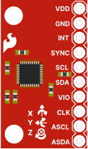
I2C address:
0x68(fixed — this board does not expose AD0)
The MPU-6050 is a 6-axis Inertial Measurement Unit (IMU) from InvenSense combining a 3-axis MEMS gyroscope and a 3-axis MEMS accelerometer in a single package. It is commonly used in drones, robots, and motion-tracking applications.
Datasheet
Section titled “Datasheet”The full MPU-6050 register map is available here.
Key Registers
Section titled “Key Registers”| Register | Address | Description |
|---|---|---|
WHO_AM_I | 0x75 | Device ID — always 0x68 |
PWR_MGMT_1 | 0x6B | Sleep, reset, clock source, temp disable |
PWR_MGMT_2 | 0x6C | Per-axis standby, low-power wake rate |
SMPLRT_DIV | 0x19 | Sample rate divider (controls FIFO fill rate) |
CONFIG | 0x1A | DLPF bandwidth setting, FSYNC |
GYRO_CONFIG | 0x1B | Full-scale range (FS_SEL), self-test |
ACCEL_CONFIG | 0x1C | Full-scale range (AFS_SEL), self-test |
FIFO_EN | 0x23 | Channel enable bits for FIFO |
INT_PIN_CFG | 0x37 | INT pin polarity (bit 7), open-drain (bit 6), latch mode (bit 5) |
INT_ENABLE | 0x38 | Interrupt enable mask |
INT_STATUS | 0x3A | Interrupt status — clears on read, deasserts INT pin |
ACCEL_XOUT_H/L | 0x3B–0x3C | X-axis acceleration |
ACCEL_YOUT_H/L | 0x3D–0x3E | Y-axis acceleration |
ACCEL_ZOUT_H/L | 0x3F–0x40 | Z-axis acceleration |
TEMP_OUT_H/L | 0x41–0x42 | Die temperature |
GYRO_XOUT_H/L | 0x43–0x44 | X-axis angular rate |
GYRO_YOUT_H/L | 0x45–0x46 | Y-axis angular rate |
GYRO_ZOUT_H/L | 0x47–0x48 | Z-axis angular rate |
USER_CTRL | 0x6A | FIFO global enable (bit 6), FIFO reset (bit 2) |
FIFO_COUNT_H/L | 0x72–0x73 | Bytes currently in FIFO |
FIFO_R_W | 0x74 | FIFO read/write port |
Sensitivity
Section titled “Sensitivity”Accelerometer (AFS_SEL in ACCEL_CONFIG bits [4:3])
Section titled “Accelerometer (AFS_SEL in ACCEL_CONFIG bits [4:3])”| AFS_SEL | Full Scale | Sensitivity |
|---|---|---|
0 | ±2 g | 16384 LSB/g |
1 | ±4 g | 8192 LSB/g |
2 | ±8 g | 4096 LSB/g |
3 | ±16 g | 2048 LSB/g |
Gyroscope (FS_SEL in GYRO_CONFIG bits [4:3])
Section titled “Gyroscope (FS_SEL in GYRO_CONFIG bits [4:3])”| FS_SEL | Full Scale | Sensitivity |
|---|---|---|
0 | ±250 °/s | 131 LSB/(°/s) |
1 | ±500 °/s | 65.5 LSB/(°/s) |
2 | ±1000 °/s | 32.8 LSB/(°/s) |
3 | ±2000 °/s | 16.4 LSB/(°/s) |
Temperature Formula
Section titled “Temperature Formula”T (°C) = TEMP_OUT / 340 + 36.53Power Management
Section titled “Power Management”PWR_MGMT_1 (0x6B) defaults to 0x40 on power-on — SLEEP bit is set. Firmware must clear it before sensor data is valid.
| Bit | Name | Description |
|---|---|---|
| 7 | DEVICE_RESET | Resets all registers to defaults; auto-clears |
| 6 | SLEEP | 1 = sleep mode (default after power-on) |
| 5 | CYCLE | Low-power sampling between sleep cycles |
| 3 | TEMP_DIS | Disable temperature sensor — TEMP_OUT returns 0x0000 |
| [2:0] | CLKSEL | Clock source (0 = internal 8 MHz oscillator) |
Burst Read
Section titled “Burst Read”The standard firmware pattern reads 14 bytes starting at 0x3B in a single I2C transaction, returning accel X/Y/Z, temperature, and gyro X/Y/Z atomically. The simulator snapshots all values at the start of this burst so all 14 bytes are consistent.
Simulation Controls
Section titled “Simulation Controls”| Control | Range | Description |
|---|---|---|
| Temperature slider | −40 to +85 °C | Ambient temperature (thermal lag τ ≈ 0.3 s) |
| Accel X/Y/Z sliders | −16 to +16 g | Acceleration along each axis (default Z = 1.0 g) |
| Gyro X/Y/Z sliders | −2000 to +2000 °/s | Angular rate along each axis |
| Gyro Bias X/Y/Z | −30 to +30 °/s | Static zero-rate offset per axis (default ≈ 2.5/−1.8/1.2 °/s) |
| Accel Bias X/Y/Z | −200 to +200 mg | Static zero-g offset per axis (default ≈ 15/−20/10 mg) |
Bias is a constant additive offset applied on top of the set value — it is not cleared by DEVICE_RESET (hardware property). Real MPU-6050 modules typically show 2–5 °/s gyro zero-rate offset and 10–50 mg accel offset uncalibrated. Firmware must measure and subtract it during a startup calibration routine.
Gaussian noise is added to every reading and scales with DLPF bandwidth (datasheet Table 13):
- Accel: σ = 400 µg/√Hz × √BW (e.g. ≈ 6.5 mg at 260 Hz, ≈ 0.9 mg at 5 Hz)
- Gyro: σ ≈ 0.01 °/s/√Hz × √BW — conservative real-world estimate (2× datasheet typical, accounts for module-level noise)
- Temperature: σ ≈ 1 °C (estimated; electrical characteristics are in PS-MPU-6000A, not the register map)
Limitations
Section titled “Limitations”- No DMP — the Digital Motion Processor (quaternion / gesture engine) is not simulated
- Pulse mode treated as latch —
INT_PIN_CFGlatch bit (bit 5) is stored; latch mode works correctly. Pulse mode (50 µs auto-deassert) is simulated as latch mode since a sub-millisecond pulse is not meaningful in simulation — firmware will still see and clear the interrupt normally - No self-test response — self-test bits in
GYRO_CONFIG/ACCEL_CONFIGare accepted but the output does not change - ASCL / ASDA are stubs — the auxiliary I2C master bus is not functional
- CLKSEL is stored but has no effect — simulation always uses wall-clock time
- SMPLRT_DIV controls the FIFO fill rate; direct burst reads always return the latest sample