

ST Nucleo-F767ZI
Cortex-M7 development board with Arduino and Morpho headers, three user LEDs, and a user button
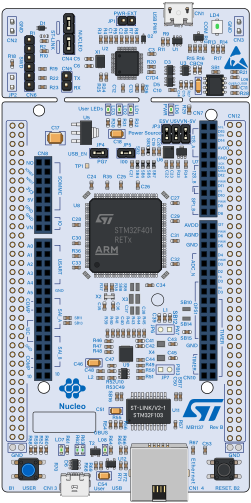
The ST Nucleo-F767ZI is a Nucleo-144 board carrying the STM32F767ZI — a 216 MHz Cortex-M7 with 2 MB of flash and 512 KB of RAM. It exposes Arduino Uno V3 headers and the full ST Morpho headers, so every bonded GPIO on the package is reachable.
Flash it with the ELF your linker produced. The board boots the way real silicon does and needs the sections and symbols an ELF carries.
Datasheet
Section titled “Datasheet”The STM32F767ZI datasheet and UM1974 (the Nucleo-144 user manual) define the pin mapping used here.
Every pin on both headers is wirable, under three naming schemes — use whichever matches your schematic:
| Naming | Examples | Notes |
|---|---|---|
| Arduino | D0–D15, A0–A5 | The Uno V3 headers |
| STM32 | PA0–PG15, PH0, PH1 | Every bonded GPIO, by port and pin |
| Board | LD1–LD3, B1, NRST, BOOT | Onboard LEDs, user button, control pads |
Aliases are intentional: D13, PA5 and LD1 are the same physical pin exposed at three connector positions.
Power and control pads — 3V3, 5V, GND, VIN, VBAT, IOREF, AVDD, E5V, U5V, VDD — plus the SWD pads (SWDIO, SWCLK, SWO) and the jumper/connector pads (JP1_1…JP7_2, CN4_1…) are all present so nothing on the board is un-wirable.
| Bus | SDA | SCL |
|---|---|---|
| I2C1 | D14 (PB9) | D15 (PB8) |
| I2C2 | PB11 | PB10 |
| I2C3 | PC9 | PA8 |
| I2C4 | PD13 | PD12 |
Pads shown are each bus’s defaults; firmware that muxes a bus elsewhere is followed automatically. I2C1 keeps its Arduino alias — that is how the header is labelled.
| Other | Pins |
|---|---|
| ST-LINK VCP | CN5_TX / CN5_RX — USART3 on PD8/PD9 |
Peripherals
Section titled “Peripherals”| Peripheral | Support | Notes |
|---|---|---|
| GPIO (ports A–K) | ✅ | |
| USART | ✅ | usart1, usart2, usart3, usart6 |
| I2C | ✅ | |
| SPI | ✅ | spi1–spi3 |
| DMA | ✅ | dma1, dma2 |
| Timers | ✅ | |
| RTC, RNG | ✅ | |
| EXTI / NVIC | ✅ | |
| Ethernet | ⚠️ | Peripheral present; no network stack attached |
| LTDC / DMA2D | ⚠️ | Present; no display output modelled |
| CAN | ⚠️ | Present; no bus modelled |
- ✅ Fully supported ⚠️ Partial / stub ❌ Not supported
Buttons
Section titled “Buttons”| Button | Behaviour |
|---|---|
| USER (B1) | Momentary GPIO on PC13. Held = high, released = low — firmware polling the pin or using EXTI sees a real press |
| RESET | Wired in the editor; the core-reset behaviour is not yet modelled |
Debug output
Section titled “Debug output”Each USART is captured as its own channel, appearing as firmware uses it — read one with run.logs({ from: "mcu1:usart3" }).
Limitations
Section titled “Limitations”- Ethernet, LTDC and CAN peripherals exist but are not connected to anything simulated
- The RESET button does not yet reset the core
- I2C transactions are serialised across the four buses — fine for a single-core MCU, which cannot be inside two blocking transactions at once