

Raspberry Pi Pico 2
RP2350 board with dual Cortex-M33 cores, the full 40-pin header, and a genuine bootrom boot path
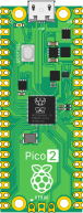
The Raspberry Pi Pico 2 carries the RP2350 — dual Cortex-M33 cores with TrustZone, 520 KB of SRAM, and 4 MB of external QSPI flash. Firmware boots through the real bootrom path, the same sequence silicon runs, rather than being dropped straight at main().
It takes an ELF or a raw .bin.
Datasheet
Section titled “Datasheet”The RP2350 datasheet and Pico 2 datasheet cover the register map, bootrom, and board pinout.
All 40 header positions are wirable.
| Group | Pins |
|---|---|
| GPIO | GP0–GP22, GP26–GP28 (26 total) |
| Ground | GND, GND2–GND8 — eight physically distinct pads |
| Power | VBUS, VSYS, 3V3 (out) |
| Control | 3V3_EN, RUN, ADC_VREF |
GP23, GP24, GP25 and GP29 are not on the header — on a real Pico 2 they are wired internally (SMPS mode select, VBUS sense, onboard LED, VSYS sense), so they are deliberately absent rather than silently doing nothing.
| Bus | Default pins |
|---|---|
| I2C0 | GP4 (SDA) / GP5 (SCL) — the pico-sdk default |
Peripherals
Section titled “Peripherals”| Peripheral | Support | Notes |
|---|---|---|
| SIO / IO_BANK0 / PADS | ✅ | Hardware-validated against a real Pico 2 |
| UART | ✅ | uart0, uart1 |
| I2C | ✅ | Including slave mode |
| SPI | ✅ | |
| PWM | ✅ | |
| Timers / ticks | ✅ | timer0, timer1 |
| Bootrom / XIP flash | ✅ | Real boot path, including XIP aliases |
| XOSC / PLL / clocks | ✅ | |
| DMA | ✅ | |
| PIO | ✅ | pio0–pio2 |
| Watchdog, POWMAN | ✅ | |
| TRNG, SHA-256, DCP | ✅ | |
| TrustZone / access control | ✅ | Hardware-validated |
| ADC | ⚠️ | Present; conversions are not modelled |
| USB | ⚠️ | Present; enumeration is not modelled |
| HSTX | ⚠️ | Present; no output modelled |
- ✅ Fully supported ⚠️ Partial / stub ❌ Not supported
Onboard LED
Section titled “Onboard LED”GP25 drives the onboard LED. It isn’t a header pin, so it can’t be wired — it lights in the editor, and every transition is recorded as a state change you can read back with run.logs({ from: "pico2:onboard_led" }).
Debug output
Section titled “Debug output”UART output is captured per tap: a uart0 channel appears when firmware prints, and uart1 alongside it as soon as it’s used.
Limitations
Section titled “Limitations”- ADC returns stub values — no analogue conversion is performed
- USB does not enumerate; BOOTSEL / DFU mode is not modelled
- The second core starts only when firmware launches it through the normal SIO FIFO sequence